Wireless Receiver for GE InterLogix
The Model 42A00-2 is compatible with all 319.5 MHz GE Security (a.k.a. ITI or Interlogix) and Caddx (crystal or SAW) Learn ModeTM 63-bit wireless transmitters.
This receiver is not compatible with 80-bit wireless transmitters.
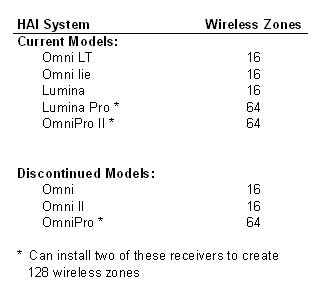
The Model 42A00-2 Supervised Wireless Receiver allows up to 64 unique wireless transmitters to report information to an HAI home control system.
The following chart shows the number of wireless zones this receiver adds to each HAI System:
DESCRIPTION
The Model 42A00-2 Supervised Wireless Receiver allows up to 64 unique wireless security transmitters to report information to an OmniLT, Omni, Omni II, Omni IIe, OmniPro, OmniPro II, Lumina, and Lumina Pro controller. The wireless transmitters replace wired door and window sensors, as well as wired smoke, motion, and glassbreak detectors. These transmitters report status information to the 42A00-2 Receiver which, in turn, processes the information and reports it to the HAI controller.
The 42A00-2 Receiver features spatial diversity, which minimizes wireless signal nulls or dead spots. The receiver may be mounted up to 1000 feet from the HAI controller.
COMPATIBLE TRANSMITTERS
The Model 42A00-2 Supervised Wireless Receiver is compatible with all 319.5 MHz GE Security (a.k.a. ITI or Interlogix) and Caddx (crystal or SAW) Learn ModeTM 63-bit wireless transmitters. This receiver is not compatible with 80-bit wireless transmitters.
INSTALLATION
Install the receiver in a central area of the premises, as high above ground as practical (allow at least a 9-inch clearance above receiver to mount the antennas).
��
The receiver should be at least 5 feet from the controller or any other electronic device.
��
The open-air range is 1000 feet; building construction will reduce the range.
Avoid areas where receiver will be exposed to moisture.
Avoid areas with excessive metal or electrical wiring. If unavoidable, mount where antennas extend above the metallic surface.
When the location of the receiver has been established:
1.
Remove the cover by inserting a screwdriver into the slot on the bottom edge of the cover, push gently to release the latch, and then lift the cover from the base.
2.
Remove the wireless receiver circuit board from the base by gently prying down the bottom latch while sliding the circuit board from under the two top latches.
3.
Hold the base against the mounting surface and mark the two (2) mounting holes (see Figure 1). Remember to allow at least a 9-inch clearance to mount the antennas.
4.
Drill a hole at each mounting hole marking and install the supplied wall anchors.
5.
Mount the base, using the supplied screws, to the wall anchors.
6.
Insert the antennas into the supplied antenna shrouds (see Figure 1).
7.
Gently slide the top of the wireless receiver circuit board under the two top latches.
8.
Snap the circuit board in at the bottom latch and secure it in place (see Figure 1).